


Get live data of your plant performance on the go.
Download the latest version of our system configuration app for your device!


Mining
Grizly feeder
Jaw Crusher
Virbation Screen
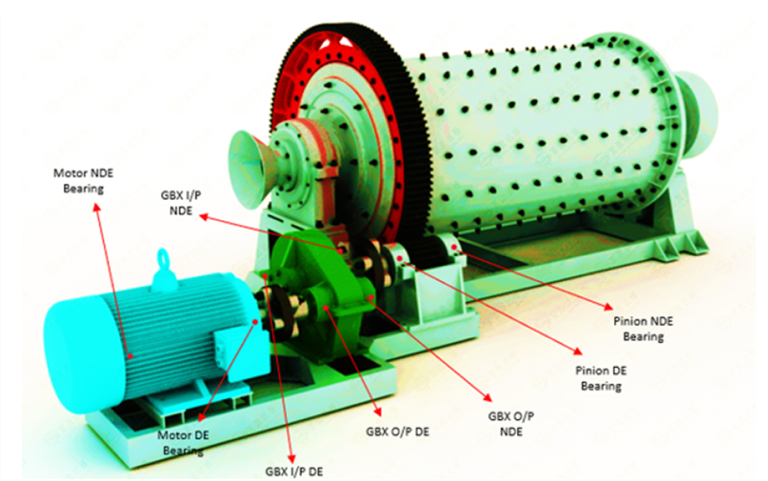
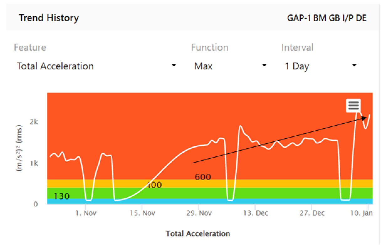
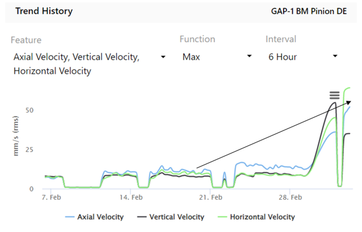
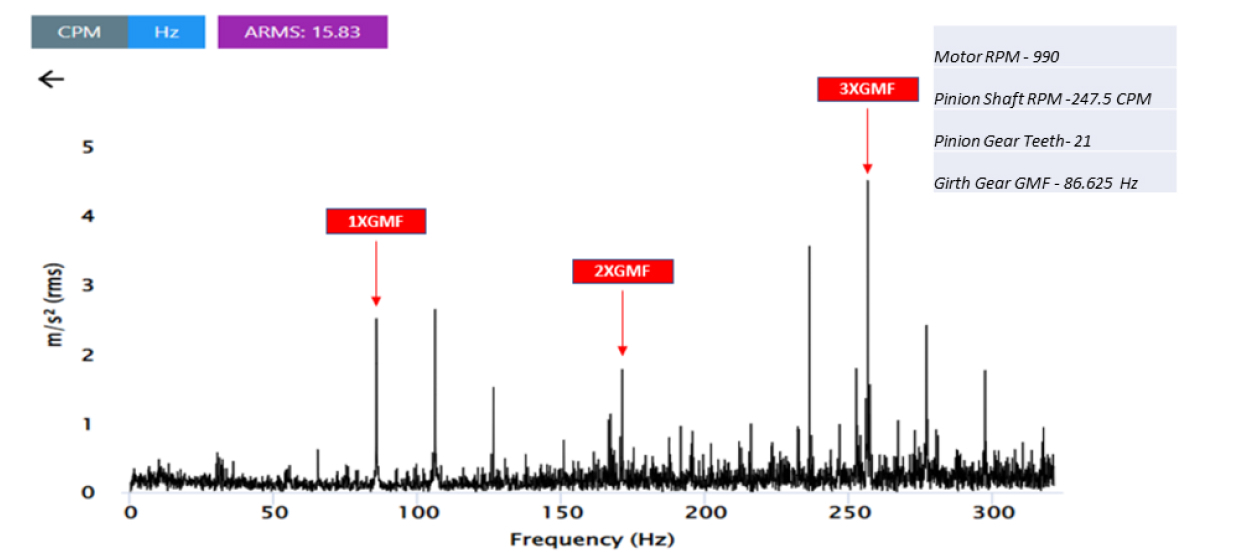
Ball Mill
Stacker Reclaimer
Cyclone Separator
Conveyor
Coke Oven
Hammer Mill
Exhaust Blower
Dedusting Fan
Cooling Water Pump
BOD Blower
Vapor Compressor
Sinter Plant
Pallet Car
Mixing Drum
Sinter Crusher
Sinter Screen
Cooller Fan
Exhaust Blower
Dedusting Fan
Conveyor
Blast Furnace
Dedusting ID Fan
Stock House Conveyor
Sinter Fines Fan
Booster Fan
VPSA Blower
VPSA Pump
BLT Charging Unit
Steel Melting Shop (SMS)
Converter Saturated Pump
Converter GCP Pump
Dedusting ID Fan
Caster Mould Pump
Caster Booster Pump
Caster Slide Gate Pump
Caster Steam Fan
Scale Pit Pump
GAC Pump
Pellet Plant
Exhaust Fan
UDD Fan
Recuperator Fan
Ball Mill
Tailing Pump
Bucket Elevator
Conveyor
Pelletizing Disc
Corex
Top Dedusting Fan
Coal Dedusting Fan
Ore Dedusting Fan
Ore Conveyor
Hot Strip Mill
Mill Stand
Mill Drive
Pinch Roll
Cradle Roll
Mill Drive
Cooling Tower
Fume Exhaust Fan
Furnace Blower
Wire Rod Mill
Mill Stand
Looper
Pinch Roll
Circluation Blower
Tandem Cooling Mill
Mill Stand
Mill Drive
Uncoiler
Recolier
Tension Reel
Delivery Looper
Fume Exhaust
Continiuos Galvanizing Line
Bridle Roll
Fume Exhaust Blower
Air Knife Blower
Coater Passivation Blower
Coating Line
Uncoiler
Recolier
FD Fan
Fume Exhaust
Bridle Roll

Raw Material Handling
Stacker Reclaimer
Crusher
Feeder
Vibrating Screen
Belt Conveyor
Raw Mill Section
Vertical Roller Mill
Classifier
Raw Mill Fan
Belt Conveyor
Raw Mill Exhaust Fan
Pyro Section
Kiln Main Drive
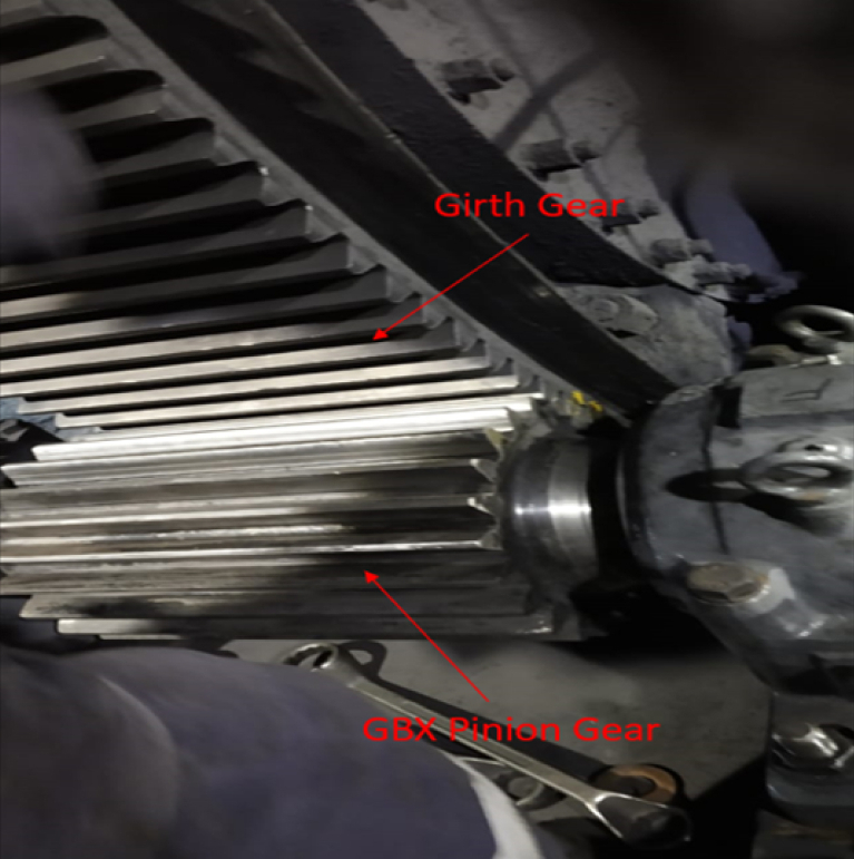
Girth Gear & Pinion
PA Fan
Preheater Fan
Bag Filter Fan
Kiln Feed Elevator
Clinker Cooler Fan
Silo
Deep Pan Conveyor
Belt Conveyor
Cement Mill
Bucket Elavator
Deep Pan Conveyor
Bag Filter Fan
Roller Press
Planetary Drive
Movable Roller
Fixed Roller
Packaging Plant
Mill Main Drive
Bucket Elevator
FD Fan
ID Fan
Powerplant
Boiler Feed Pump
PA Fan
SA Fan
ID Fan
CEP Pump
Vacuum Pump
Cooling Water Pump
Demineralization Pump
Gas Turbine
Cooling Tower Fan

Green Anode Plant (GAP)
Ball Mill
Bucket Elevator
ID Fan
Kneader
Paste Mixer
Baking Furnace
FTA Blower
FTA Compressor
FTP ID Fan
Rodding
Autogenous Mill
Belt Conveyor
Shot Blast Unit
Dust Collector Fan
Butt Press Pump
Potline
Circulation Blower
ID Fan
Belt Conveyor
Cast House
Ingot Transfer Fork
Cooling Conveyor
Layer Conveyor
Stack Conveyor
Casting conveyor
Wire Rod Mill
Cooling Tower
Saw Cutter
Air compressor
Pit Pump
Crane
Billet Cutter
Rolling
Rough Rolling Stand
Finish Rolling Stand
Anealing
Cooler Fan
Powerplant
Boiler Feed Pump
PA Fan
SA Fan
ID Fan
CEP Pump
Vacuum Pump
Cooling Water Pump
Demineralization Pump
Gas Turbine
Cooling Tower Fan

Banbury Mixer
Master Mixer
TSS Screw
TSS Calender gearbox
Dust Collecting Blower
Milling Section
Hold Mill
Feed Mil
Cracker Mill
Extruder
Duplex Extruder
Triplex Extruder
Quadraplex Extruder
Cushion Feed Extruder
Pork chop Extruder
Belt Extruder
Bead Construction
Bead Apex Extruder
Thread Applicator
Strip Winding Extruder
Inner Liner Calendering
Inner liner extruder
Inner Liner Roll
Fabric Cord Calendering
Pork chop Extruder
Calendar Hold Mill
Calendar Feed Mill
Calendar Rolls (4 roll section)
Cushion Calendar
Steel Belt Calendering
Steel Belt Cutting
Fabric Ply Cutting
Tyre Building
Curing & Inspection

Pulping
Digester
Mixer
Reactor pump
Tower feed pump
Press Feed Pump
Pulp Press Roll
Disc Filter
Twin Roll press
Vacuum Drum Washer
Evaporator
Chemical Recovery
Weak Chlorine Blower
Chlorine Supply Pump
Air Compressor
Caustic Pump
Recovery Boiler Pump
ID Fan
Scrubber Unit
Slaker
Washer
Refiner
Bleacher
Forming
Breast Rolll
Table Roll
Dandy Roll
Couch Roll
Wire Roll
Dyring
Drying Cylinder
Felt Roll
Vaccum Roll
Yankee Cylinder
Calendaring
Top Roll
Intermediate Roll
Queen Roll
Deflection Roll
Compensating Roll
Reeling
Reel Drum Roll
Reel Spool Roll
Rider Roll
Winder Drum Roll
Water Treatment Plant
Raw Water Pump
Dosing Pump
Return Sludge Pump
Air Compressor
Powerplant
Boiler Feed Pump
PA Fan
SA Fan
ID Fan
CEP Pump
Vacuum Pump
Cooling Water Pump
Demineralization Pump
Gas Turbine
Cooling Tower Fan